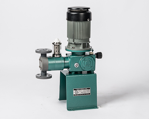
DHD Series
Hydraulic Double Diaphragm Type Dosing Pumps
![]()
Features & Cautions
- Stable discharging precision
Completely leak proof glandless pump by high precision plunger. - Realized compect & low cost pump
For the first time at pump head part imtroduced mass production technique including mechanism of oil pressure part and drive part to realization of stable quality and low cost. - Reliable high hydraulic mechanism
Developed by Dong-il techmique where has been acknowledged to process pump, It’s not only compect type but also reliable high oil pressure mechanism. - Excellent durability of pump’s drive part
Used cam mode reducer compact and steady reliable high worm gear type. And complete air-tight oil base lubrication mode. So it’s not only installed outside of building but also showing excellent durability at long time continuous operation. - Implement relief valve inside pump to prevent from damage by abnormal pressure.
- Above specifications are that should be changeable due to improvement etc without any notice.
![]()
Capacity – Pressure Selection Table
| MODEL | No. of stroke(SPM) | Dis. Capacity(mL/min) | Max.dis Pressure(kg/㎠) | Plunger dia. (Mm) |
Motor Output(kW) |
Joint Size | ||||
| 50Hz | 60Hz | 50Hz | 60Hz | sus | pvc | |||||
| DHD | 10 | 96 | 116 | 41 | 50 | 25 | 10 | Φ15 | 0.2 | 15A KS16K(SUS) KS10K(PVC) |
| 11 | 96 | 116 | 82 | 100 | ||||||
| 20 | 48 | 58 | 124 | 150 | Φ25 | |||||
| 21 | 96 | 116 | 260 | 320 | ||||||
| 31 | 96 | 116 | 430 | 520 | 20 | 10 | Φ35 | |||
| 60 | 48 | 58 | 660 | 800 | 20 | 10 | Φ60 | 0.4 | 20A KS16K(SUS) KS10K(PVC) |
|
| 61 | 96 | 116 | 1320 | 1600 | 15 | 10 | ||||
| 71 | 96 | 116 | 2600 | 3200 | 15 | 10 | Φ80 | |||
| 80 | 48 | 58 | 6500 | 8000 | 12 | 10 | Φ120 | 0.75 | 25A KS16K(SUS) KS10K(PVC) |
|
| 81 | 96 | 116 | 14000 | 17000 | 12 | 8 | 0.75 | |||
![]()
Principle of Hydraulic Regulator
- ABNORMAL PRESSURE RISE
When an abnormal pressure occurs in the discharge side piping, Relief valve is lifted, and silicone oil is released.
This relief pressure can be adjusted by moving up and down relief pressure adjusting nut, by using pressure adjusting tool. - RETURN TO NORMAL PRESSURE
When abnormal pressure is removed and a normal pressure recovered.
A negative pressure builds up at every suction process of the piston.
Then the oil refill valve is lowered. And the released silicon oil is sucked into the pump up to proper level.
This suction pressure can be adjusted by the suction pressure adjusting nut.
![]()
DHD Series performance graph

![]()
Sectional Drawing
 |
Liquid end parts name | |
| a | Pump head | |
| b | Ball valve | |
| c | Ball guide | |
| d | Ball seat | |
| e | Lap joint | |
| Hydraulic parts name | ||
| A | Front diaphragm | |
| B | Rear diaphragm | |
| C | Silicone oil | |
| D | Pistion O-Ring | |
| E | Piston | |
| Hydraulic Regulator parts name | ||
| 1 | Suction pressure adjusting nut | |
| 2 | Cap | |
| 3 | Regulator cap | |
| 4 | Suction pressure adjusting spring | |
| 5 | Relief valve guide | |
| 6 | Lock nut | |
| 7 | Relief pressure adjusting nut | |
| 8 | Relief pressure adjusting spring | |
| 9 | Oil refill valve | |
| 10 | Regulator cover | |
| 11 | Relief valve | |
![]()
Dimension (Unit/mm)

| Type | A | B | C | D | E | F | G | H | I | J | K | L | M |
| DHD 10,11 | 605 | 411 | 342 | 262 | 165 | 179 | 210 | 240 | 145 | 185 | 136 | 10 | 15A |
| DHD 20,21,31 | 605 | 410 | 340 | 263 | 176 | 175 | 210 | 240 | 145 | 185 | 135 | 10 | 15A |
| DHD 60,61,71 | 605 | 435 | 342 | 263 | 235 | 144 | 210 | 240 | 145 | 185 | 168 | 10 | 20A |
| DHD 80,81 | 718 | 556 | 387 | 331 | 329 | 161 | 290 | 280 | 320 | 260 | 176 | 10 | 25A |
Get in touch
| PT. Dutasarana Sumberjaya |
|---|
| Jl. Kinabalu No.79, Surabaya ID 60252 |
| +62-031-5323079 |
| info@dutasaranasumberjaya.com |
| dutasaranasumberjaya@yahoo.co.id |
| www.dutasaranasumberjaya.com |